
GFRC Columns & Capitals
GFRC columns from MIRU are shells, not structure. They wrap the RCC or steel column your engineer has already designed — a thin cast casing that carries the profile, the flutes, the capital, the ornament — while the frame underneath carries the load. Specify the geometry; we build it as a jacket that closes around what is already standing.
Every column starts as your issued drawing rebuilt as an exact 3D model. Shaft taper, entasis, capital ornament and joint positions are resolved on screen before any mold is cut. Where the profile is ornamental or tightly curved, molds are CNC-machined in-house.
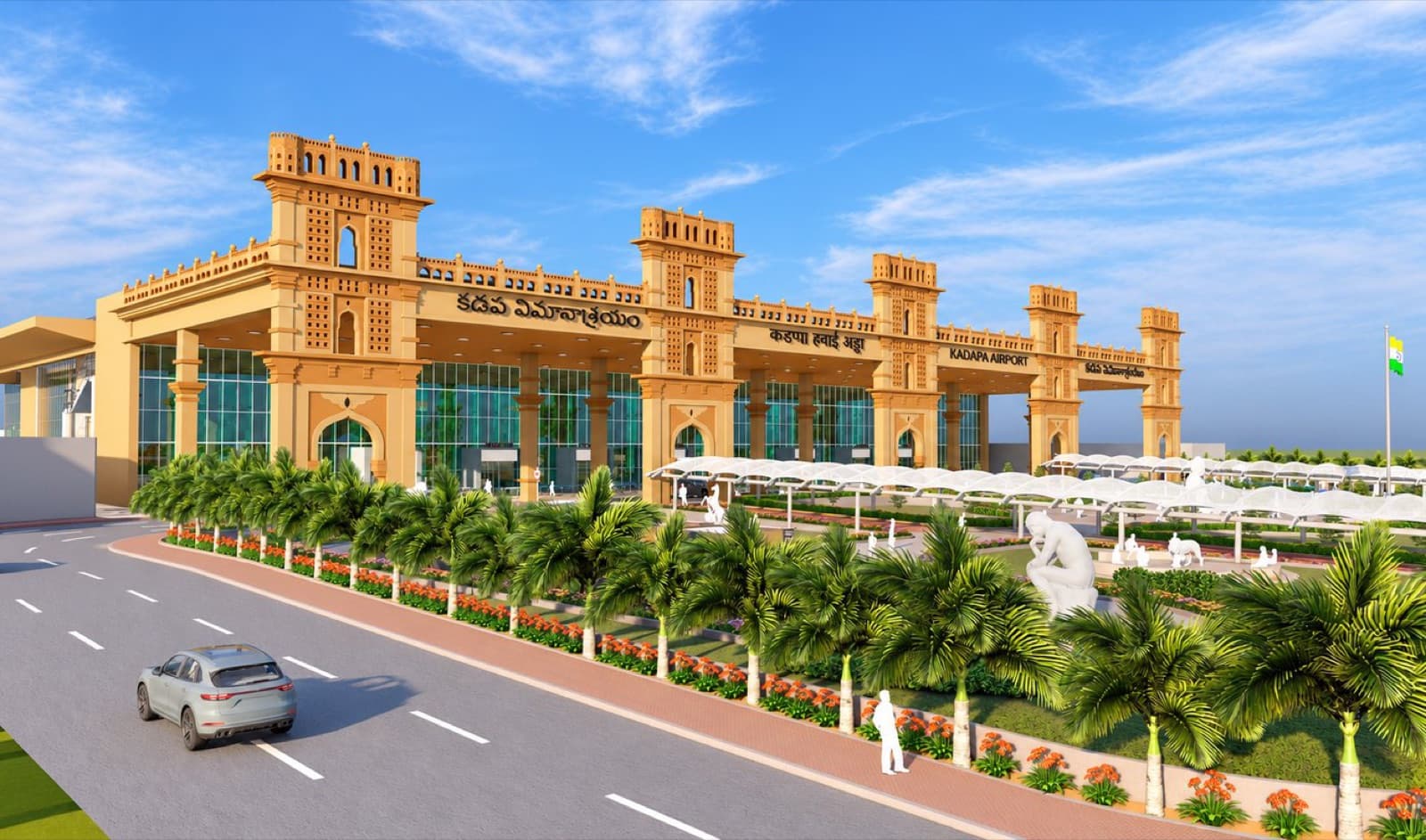
The material is no-polymer spray-up GFRC with AR-glass fibre, flexural-tested to ASTM C947 in our own lab at Kota. On Kadapa airport terminal, clad columns with cornice bands and arches ran as part of 72 element families — 2,203 pieces in all.
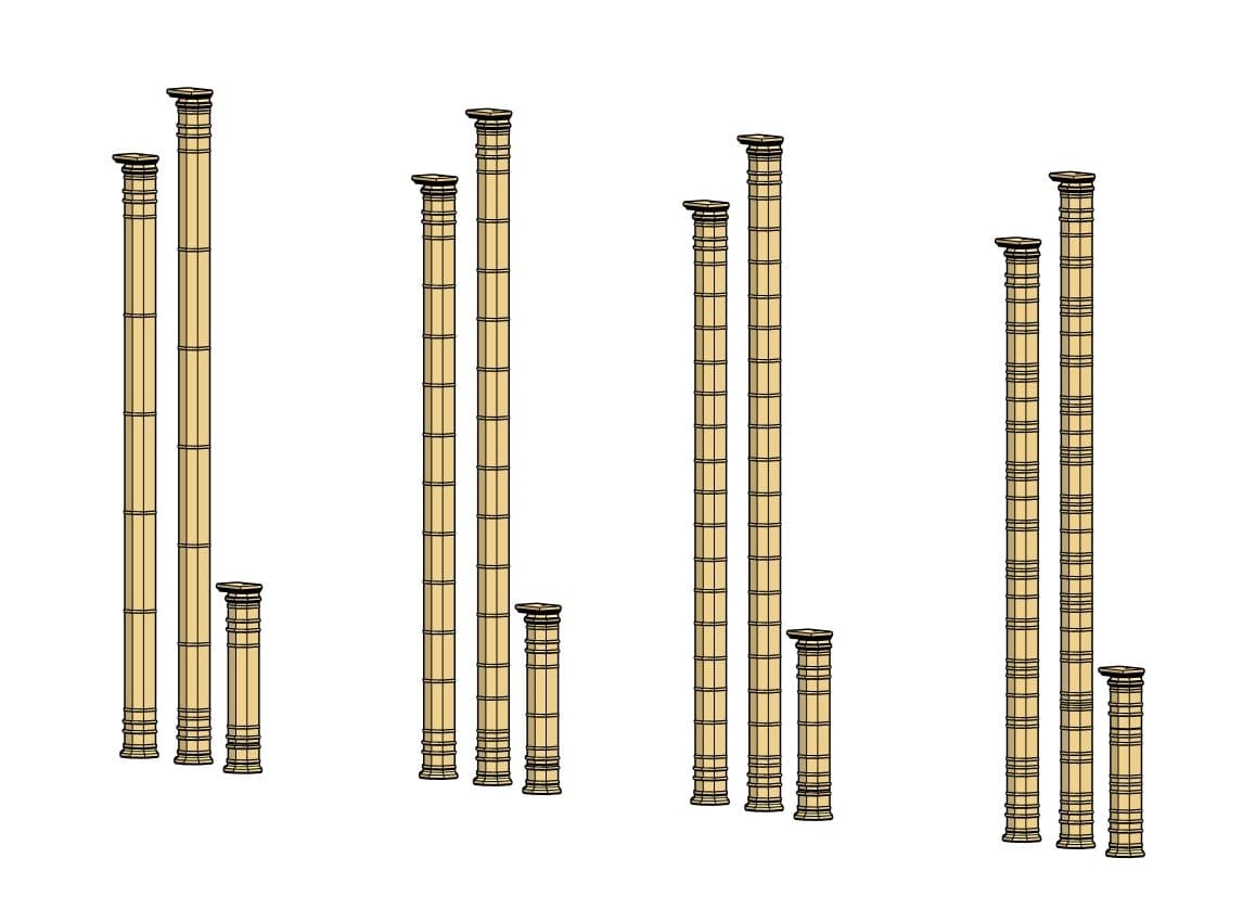
What we deliver
GRC column shells
Segmented casings for round, square and fluted structural columns. Split vertically or into stacked drums at the modelling stage, sized to handling and site access.
GRC capitals
Cast as separate elements that seat on the shaft shell. Classical orders or project-specific designs, rebuilt in 3D from your drawings and machined into molds before a single casting.
Full-height column cladding
Shells split into vertical segments that stack and close over a concealed frame — the method behind Jammu airport's full-height columns: 42 element families, 1,003 pieces.
Fluted, tapered and entasis shafts
Curvature is geometry, not craft judgement. Taper and entasis come off the 3D model exactly, so every shell in a family is interchangeable.
Bases and plinth casings
Base profiles cast to close the shaft to floor level, with fixing and junction details resolved on the shop drawings, not on site.
Embossed and ornamental shells
Relief and emboss options are studied on the 3D model before mold work, so what is approved on screen is what the mold reproduces.
Cornice, arch and bullnose junctions
Where columns meet arches and cornice bands — as on Kadapa airport terminal — junction pieces are cast as their own element families, not improvised on site.
Installer drawings with every lot
Each dispatch is tracked and itemised, with drawings that show which segment stacks where and in what order the shell closes.
From your drawings to installed elements
Your issued DWG or GFC set comes in; we rebuild the column line as exact 3D geometry — shaft, capital, base, joints — and return shop drawings for approval. Segment splits are decided here: where the shell divides vertically, where drums stack, where the closing piece lands. Molds follow, engineered in-house and CNC-machined where capitals, flutes or emboss demand it.
Casting is no-polymer spray-up with AR-glass fibre from Nippon Electric Glass and Owens Corning. Every session is logged — mix batch, QC check, cure — and coupons are flexural-tested to ASTM C947 against internal acceptance targets for MOR and LOP. Finished shell segments and capitals leave in tracked, itemised lots with installer drawings.
Built at MIRU

The factory, measured.
from our production system, July 2026Questions
Are GFRC columns structural?
No. MIRU casts column shells and capitals — casings that wrap a structural column designed by your engineer. The RCC or steel member carries the load; the GFRC carries the profile, the flutes and the ornament. Because the shell is cast thin relative to precast, it adds little weight and can be fitted around columns that are already built.
How do the shells fix to the existing structure?
Shells arrive split into segments — vertical strips, stacked drums, or both, decided at the 3D modelling stage from your issued drawings. Segments stack and close over a concealed frame fixed back to the structural column; the last segment closes the ring. This is the method behind Jammu airport's full-height columns. Fixing details and stacking sequence come with the installer drawings in every dispatched lot.
What ornament and finish options are there for capitals?
Ornament is resolved before any mold work. Your capital or emboss pattern is rebuilt in 3D, reviewed on screen, and only then machined into a mold — CNC where the relief is tight or perforated. The finish comes off the mold face; textures and pigmented mixes are settled at sample approval, so the production run matches what was signed off.
How should the material be specified in a tender?
Call for no-polymer spray-up GFRC with alkali-resistant glass fibre — ours is from Nippon Electric Glass and Owens Corning — flexural-tested to ASTM C947. MIRU's internal acceptance targets are MOR 12 N/mm² and LOP 6 N/mm², checked in our in-house test lab. Issue your GFC or DWG set and we return shop drawings built from an exact 3D model of every column family.
Why GFRC over precast concrete or plaster for column cladding?
Weight and fidelity. GFRC casts thin relative to precast, so a full-height shell can be lifted, stacked and fixed without heavy plant, and adds little dead load to the frame. Against plaster or in-situ work, the geometry is exact: every shell comes from a machined mold built off a 3D model, so each column in the run is identical. And the material is tested in a lab, not assumed.
How does supply run on a live project?
Column families are produced against a logged schedule — every casting session, mix batch and QC check is recorded in the digital production system. Segments dispatch from Kota in tracked, itemised lots, each with its challan and installer drawings, so the site team can reconcile what arrived against what was cast. Across live projects, that system has put 84,000+ sq ft on the road.
Have a facade on the drawing board?
Send the drawings. We reply with an element breakdown, a mold plan and a production timeline.
Start a project